Privacy statement: Your privacy is very important to Us. Our company promises not to disclose your personal information to any external company with out your explicit permission.
Translated with www.DeepL.com/Translator (free version)

In the mechanical transmission, rotary motion into reciprocating linear motion or reciprocating linear motion into rotary motion, generally is the use of eccentric parts to complete. For example, the lathe headbox with eccentric workpiece driven by the lubrication pump, the crankshaft in the car engine, etc..
Eccentric shafts and eccentric sleeves are generally machined on lathes. Their processing principle is basically the same; mainly in terms of clamping measures, that is, the need to process the eccentric part of the axis to find the axis of rotation with the lathe spindle coincident. There are five general methods of turning eccentric workpieces, i.e. turning eccentric workpieces on a three-jaw chuck, turning eccentric workpieces on a four-jaw chuck, turning eccentric workpieces between two tops, turning eccentric workpieces on an eccentric chuck, and turning eccentric workpieces on a special fixture.
Process analysis of traditional turning eccentric parts
1.Use of three-jaw chuck for clamping
(1) Turning method
The eccentric workpiece with short length can be turned on the three-jaw chuck. First, the non-eccentric part of the eccentric workpiece is turned, and then a shim of pre-selected thickness is placed between any of the chuck jaws and the workpiece joint surface, and the workpiece can be turned after the bus and eccentric distance are corrected and the workpiece is clamped.
The thickness of the shim can be calculated using the approximate formula; shim thickness X = 1.5e (eccentricity). To make the calculation more accurate, the shim thickness is calculated and adjusted by adding the eccentricity correction k to the approximate formula, which is: shim thickness x = 1.5e + k
k≈1.5∆e
Δe=e - e measurement
where: e - eccentricity of the workpiece.
k - correction value of eccentricity distance, positive or negative determined by actual measurement results.
△e --- actual measured eccentricity error after trial cutting;
e measurement --- after trial cutting, the actual measured eccentricity distance.
(2) Measurement and inspection of eccentric workpiece
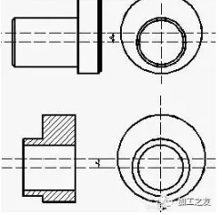
Workpiece adjustment and correction of the side bus and eccentric distance is mainly carried out on the lathe using a percentage table with a magnetic table base (as shown below (c) right) until it meets the requirements before turning. After the workpiece has been turned, a final check is carried out to determine whether the eccentric distance meets the requirements. The method is to put the workpiece into the v-iron, use the percentage meter to measure at the eccentric circle, slowly turn the workpiece and observe its runout.
2.Use the four-jaw single-action chuck for clamping
The correcting steps are
The following are the steps to find the correctness of the workpiece: 1) put the scribed line on the four-jaw chuck. In the clamping, first adjust the two jaws of the chuck, so that it is asymmetrical position, the other two jaws into a symmetrical position, the workpiece eccentric circle line in the centre of the chuck (see above right)
The eccentric circle is corrected by placing a small flat plate and scribing disc on the bed, with the needle tip aligned with the eccentric circle line. Then align the needle tip with the horizontal line of the outer circle, as shown in the picture below left, and check from left to right that the horizontal line is level. Turn the workpiece by 90° and check the other horizontal line in the same way, then tighten the clamping foot and review the workpiece clamping.
Once the workpiece is aligned, tighten the four jaws again and cut. In the initial cutting, the feed should be small, the depth of cut should be shallow, and so on after the workpiece turned round the cutting amount can be increased appropriately, otherwise it will damage the turning tool or make the workpiece shift. The following figure (c) left.
Both of the above methods are more commonly used machining methods, but both have disadvantages. Clamping is more troublesome, not easy to find the correctness, easy to produce errors. They are also not suitable for mass production. In view of the above disadvantages, I designed an eccentric fixture specifically for mass production. It has been put into production and has achieved certain results.
Design of a new special eccentric fixture
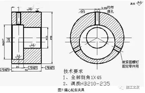
Eccentric wheel car jig is mainly used for mass production of eccentric parts, the following with the jig parts diagram (such as Figure 1).
Clamping time to hit the table to correct Ф60 bore, to ensure that the shape and position of the parts tolerance requirements. Clamping method is the left end of the following fixture clamping workpiece, through the percentage table correction, the right end of the clamping on the three-jaw self-centering chuck.

Machining example
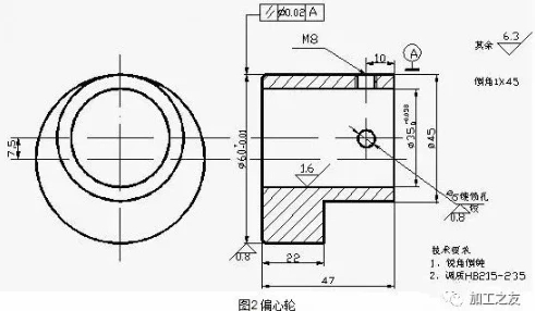
Machining of an eccentric wheel using an eccentric wheel turning jig, the following part drawing and machining process card for the eccentric wheel are shown.

The focus of this paper is on the clamping method for mass production of eccentric workpieces and the design of a matching fixture through which clamping is carried out, saving a lot of time in setting and improving the accuracy requirements. Using the concept of the fixture we can also process more eccentric workpieces, mainly by designing fixtures with different eccentric distances for clamping. The eccentric wheel turning fixture is simple to manufacture and can therefore be widely promoted to improve economic efficiency.
Previous: What Is A Spur Gear

Privacy statement: Your privacy is very important to Us. Our company promises not to disclose your personal information to any external company with out your explicit permission.

Fill in more information so that we can get in touch with you faster
Privacy statement: Your privacy is very important to Us. Our company promises not to disclose your personal information to any external company with out your explicit permission.