Although the structure of the mold may vary depending on the type and performance of the plastic, the shape and structure of the plastic product , and the type of the injection machine, the basic structure is uniform. The mold is mainly composed of a gating system, a temperature control system, a molded part and a structural part. The gating system and the molded part are in direct contact with the plastic and vary with the plastic and the product. It is the most complicated and most varied part of the mold, and requires the highest degree of smoothness and precision.
The injection mold consists of two parts: a movable mold and a fixed mold. The movable mold is mounted on the moving template of the injection molding machine, and the fixed mold is mounted on the fixed template of the injection molding machine. In the injection molding, the movable mold and the fixed mold close constitute a casting system and a cavity, and when the mold is opened, the movable mold and the fixed mold are separated to take out the plastic product. In order to reduce the heavy mold design and manufacturing workload, most of the injection molds use standard mold bases.
Gating system
The gating system refers to the part of the flow path before the plastic enters the cavity from the nozzle, including the main channel, the cold material hole, the shunt channel and the gate. The gating system, also known as the runner system, is a set of feed channels that direct the plastic melt from the injector nozzle to the cavity, typically consisting of a main flow path, a split runner, a gate, and a cold feed pocket. It is directly related to the molding quality and production efficiency of plastic products.
Mainstream road
It is a passage in the mold that connects the nozzle of the injection molding machine to the runner or cavity. The top of the main flow path is concave to engage the nozzle. The diameter of the main entrance should be slightly larger than the diameter of the nozzle (0.8mm) to avoid flashing and prevent the interception of the two due to inaccurate connection. The diameter of the inlet depends on the size of the product, which is generally 4-8mm. The diameter of the main flow path should be enlarged inward by an angle of 3° to 5° in order to demold the flow path.
Cold pocket
It is a cavity at the end of the main channel to capture the cold material generated between the two injections at the end of the nozzle to prevent blockage of the runner or gate. If the cold material is mixed into the cavity, internal stress is easily generated in the manufactured product. The cold pocket has a diameter of about 8-10 mm and a depth of 6 mm. In order to facilitate demolding, the bottom is often carried by the stripper. The top of the demolding rod should be designed as a zigzag hook or a depression groove so that the main channel can be smoothly pulled out during demolding.
Split runner
It is a channel connecting the main channel and each cavity in a multi-slot mold. In order for the melt to fill the cavities at a constant velocity, the arrangement of the runners on the mold should be symmetric and equidistant. The shape and size of the cross-section of the runner have an effect on the flow of the plastic melt, the release of the product, and the ease of mold manufacture.
If the flow is of equal amount, the flow path resistance with a circular cross section is the smallest. However, because the specific surface of the cylindrical flow passage is small, it is unfavorable for the cooling of the shunting passage, and the shunting passage must be opened on the two mold halves, which is laborious and difficult to align. Therefore, a trapezoidal or semi-circular cross-section runner is often used and is placed on one half of the mold with the stripper. The runner surface must be polished to reduce flow resistance to provide faster filling speed. The size of the runner is determined by the variety of plastics, the size and thickness of the product. For most thermoplastics, the cross-sectional section width is no more than 8m, and the extra large is 10-12m, and the extra small is 2-3m. The cross-sectional area should be minimized to meet the needs, in order to increase the shunting material and extend the cooling time.
Gate
It is the channel that connects the main channel (or shunt) to the cavity. The cross-sectional area of the channel can be equal to the main channel (or shunt), but it is usually reduced. So it is the smallest part of the cross-sectional area of the entire runner system. The shape and size of the gate have a great influence on the quality of the product.
The role of the gate is:
A. Control the flow velocity:
B. In the injection, the melt can be prevented from flowing back due to the early condensation of the molten material in this part:
C. The molten material is subjected to strong shearing to raise the temperature, thereby lowering the apparent viscosity to improve the fluidity:
D. It is convenient to separate the product from the runner system. The design of the gate shape, size and location depends on the nature of the plastic, the size and structure of the article. Generally, the cross-sectional shape of the gate is rectangular or circular, and the cross-sectional area should be small and the length should be short, which is not only based on the above effects, but also because the small gate becomes larger, and the large gate is difficult to be reduced. The location of the gate should generally be chosen where the product is thickest and does not affect the appearance.
The gate size should be designed to take into account the nature of the plastic melt. The cavity is the space in which the plastic product is molded in the mold. The components used to form the cavity are collectively referred to as molded parts.
Each molded part often has a unique name. The molded part constituting the outer shape of the product is called a concave mold (also called a female mold), and the inner shape (such as a hole, a groove, etc.) constituting the inner shape of the product is called a core or a punch (also called a male mold). When designing a molded part, the overall structure of the cavity is first determined according to the properties of the plastic, the geometry of the product, the dimensional tolerances, and the requirements for use. Secondly, the position of the parting surface, the gate and the vent hole, and the demolding mode are selected according to the determined structure. Finally, the design of each part is carried out according to the size of the control item and the combination between the parts is determined. The plastic melt has a high pressure when it enters the cavity, so the molded parts should be properly selected and checked for strength and stiffness. In order to ensure the smooth and beautiful surface of the plastic products and easy demoulding, the surface in contact with the plastic has a roughness Ra>0.32um and is resistant to corrosion. Molded parts are generally heat treated to increase hardness and are made of corrosion-resistant steel.
Temperature control system
In order to meet the mold temperature requirements of the injection process, a temperature adjustment system is required to adjust the temperature of the mold. For injection molds for thermoplastics, the cooling system is primarily designed to cool the mold. The common method of mold cooling is to open a cooling water channel in the mold, and use the circulating cooling water to take away the heat of the mold; in addition to using the cooling water channel hot water or steam, the heating of the mold can also install electricity inside and around the mold. Heating element.
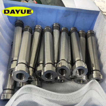
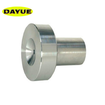
Molded part
Molded parts refer to various parts that make up the shape of the product, including moving molds, fixed molds and cavities, cores, forming rods, and exhaust ports. The molded part consists of a core and a die. The core forms the inner surface of the article and the die forms the outer surface shape of the article. After clamping, the core and cavity form the cavity of the mold. According to the process and manufacturing requirements, sometimes the core and the die are made up of several pieces, sometimes made into a whole, and only the inserts are used in the parts that are easily damaged and difficult to process.
exhaust vent
It is a trough-shaped air outlet opened in the mold to discharge the original and the gas brought in by the melt. When the molten material is injected into the cavity, the air originally stored in the cavity and the gas brought in by the melt must be discharged to the outside of the die through the exhaust port at the end of the flow, otherwise the product will have pores and poor connection. The filling is not full, and even the accumulated air burns the product due to the high temperature generated by compression. In general, the vent hole can be located at the end of the flow of the melt in the cavity or on the parting surface of the mold. The latter is a shallow groove having a depth of 0.03-0.2 mm and a width of 1.5-6 mm on one side of the die. During the injection, the vent hole does not have a lot of melt oozing out, because the melt will cool and solidify there to block the passage. Do not point the opening of the exhaust port to the operator to prevent the fuse from accidentally squirting and injuring people. In addition, the matching gap between the ejector rod and the ejector hole, the matching gap between the top block and the stripper and the core may be utilized to exhaust.
Structural part
It refers to the various parts that make up the mold structure, including: guiding, demoulding, core pulling and various parts of the parting. Such as front and rear splint, front and rear buckle template, bearing plate, pressure column, guide column, stripping plate, stripping rod and return rod.
Guide member
In order to ensure accurate alignment of the moving and fixed molds during mold clamping, guide members must be provided in the mold. In the injection mold, four sets of guide columns and guide sleeves are usually used to form the guide members, and sometimes the inner and outer tapered surfaces are respectively arranged on the movable mold and the fixed mold to assist the positioning.
2. Launching agency
In the mold opening process, an ejection mechanism is required to push or pull the plastic product and its aggregate in the flow path. A fixing plate and a push plate are introduced to hold the push rod. A reset lever is generally fixed in the push rod, and the reset lever resets the push plate when the mold is fixed and fixed.
3. Side core pulling mechanism
Some plastic products with undercuts or side holes must be laterally typed before being pushed out, and the side cores can be smoothly released after being pulled out. In this case, a side core pulling mechanism is required in the mold.


 May 20, 2020